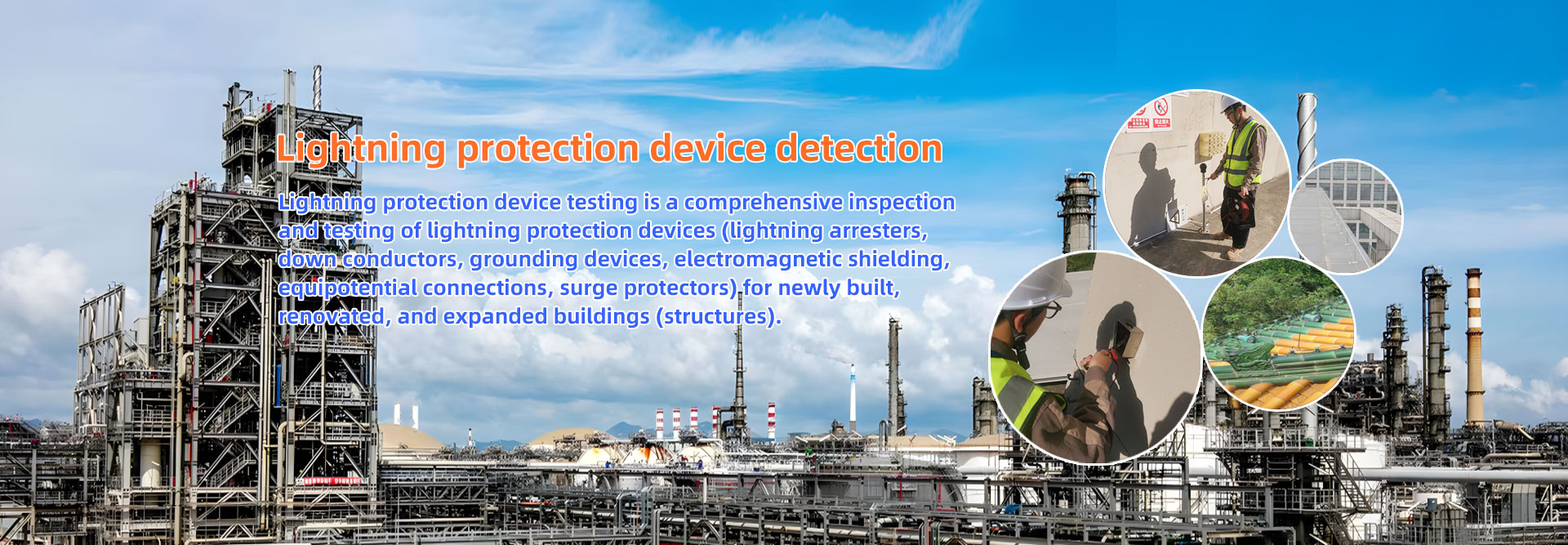
Home / Services / Lightning protection detection construction

Lightning protection detection construction testing items

Lightning protection testing refers to the activity of inspecting the lightning protection devices of buildings and structures, with the aim of determining whether the lightning protection devices comply with national or industry standards, design requirements, identifying potential safety hazards, and preventing or reducing the occurrence of lightning disasters. It is also an important component of lightning protection engineering and a necessary measure to ensure the safe operation of buildings.


Lightning arrester

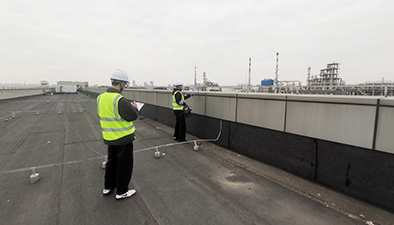
(1) Check the electrical connections between the lightning arrester and other exposed metal objects on the roof of the building, the electrical connections with lightning protection down conductors, and the equipotential connections of roof facilities.
(2) Check whether the position of the lightning arrester is correct, whether the welded joints are full and without omissions, whether the anti loosening parts such as bolt fixation are complete, whether the anti-corrosion paint applied to the welded parts is complete, and whether the lightning arrester is corroded by more than 1/3. Whether the lightning strip is flat and straight, whether the spacing between the fixed point supports is uniform and reliable, and whether the spacing between the lightning strip supports meets the requirement of no more than 1m in horizontal straight line distance. Can each supporting component withstand a vertical tensile force of 49N (5kgF).

Downlead

(1) For the first detection of the down conductor, the concealed engineering records of the lightning protection construction of the down conductor should be checked
(2) Check if the exposed down lead is straight and free from sharp bends. Whether the spacing between the supporting components of the down conductor meets the requirements of 0.5-1.5m for horizontal straight sections, 1.5-3.0m for vertical straight sections, and 0.3-0.5m for curved sections
(3) Check if the welding joints of the down conductor, lightning arrester, and grounding device are corroded, if there are any paint omissions, and if there are any protective facilities near the ground
(4) During the first inspection, use a tape measure to measure the distance between each adjacent two down conductors, record the total number of down conductors arranged, and each down conductor is a detection point, numbered in order for inspection
(5) During the first inspection, use a vernier caliper to measure the specifications and dimensions of each down conductor
(6) The distance between the exposed down conductor and other nearby electrical circuits should generally not be less than 1.0m
(7) Check if the settings of the disconnect card meet the following requirements:
When using multiple down conductors, it is advisable to install disconnect cards between 0.3-1.8m above the ground on each down conductor
When using concrete reinforcement and steel columns as natural down conductors and also using foundation grounding bodies, it is not necessary to set up disconnecting clamps. When using reinforcement as down conductors, several connecting plates should be set up at appropriate locations indoors and outdoors, which can be used for measurement, manual grounding, and equipotential connection. When using only steel bars as down conductors and artificial grounding bodies buried in soil, grounding body connection plates should be installed at a distance of not less than 0.3m from the ground on each down conductor. When using artificial grounding bodies buried in soil, a disconnect card should be installed, and its upper end should be welded to the connecting plate or steel column. There should be clear markings at the connection plate.

Grounding device

During the first inspection, the concealed engineering records should be checked, and the structure and installation position of the grounding device should be checked. The burial spacing, depth, and installation method of the grounding body should be checked, and the material, connection method, and anti-corrosion treatment of the grounding device should be checked.
Check if there is any settlement in the soil filling of the grounding device, and backfill the soil in the settlement area. Check if the grounding device has been broken due to excavation, pipeline laying, or tree planting. If the grounding device is broken, it should be repaired.
During the first inspection, the vertical distance between adjacent grounding bodies should be checked, and it is required that the vertical distance between the two grounding bodies should be greater than 20m.

Magnetic shield

Building or line shielding plays an important role in resisting lightning electromagnetic pulses, but the magnitude of this effect, that is, the shielding effectiveness, directly affects the ability of electronic systems to resist lightning electromagnetic pulses.
The basic requirements for building shielding bodies are generally to use the metal shielding of the roof, the metal shielding of the facade (including external metal doors, windows, balcony metal railings, etc.), the metal shielding of the floors (including the steel bars of each floor slab), etc. They should be connected to each other by welding or binding, and connected to the lightning protection device at the same potential.

Lightning equipotential bonding

Large metal object connection detection:
Check the connection between large-sized metal objects such as equipment, pipelines, structures, pressure equalization rings, steel frames, steel windows, discharge pipes, cranes, metal floors, elevator tracks, railings, etc. and the shared grounding device. If a solid line connection has been made, the connection quality, material and size of the connecting conductor should be further checked, and the grounding resistance value should be measured.
Parallel laying of long metal object detection:
Check the metal wire crossing situation of pipes, structures, and cable metal sheaths that are parallel or cross laid, with a clear distance less than the specified required value. If a solid line has been crossed, further inspection should be conducted on the quality of the connection, the material and size of the connecting conductor, and the grounding resistance value should be measured.
Inspection of long metal bends, valves, and other connecting objects:
Check the transition resistance at the joints of long metal objects such as elbows, valves, flanges, etc. in the first type of lightning protection buildings. When the transition resistance is greater than 0.03 Ω, check whether there is a jumper metal wire, and check the quality of the connection, the material and size of the connecting conductor, and measure its grounding resistance value.
Total equipotential bonding strip detection:
Check the overall equipotential connection status from LPZ0 zone to LPZ1 zone. If two or more connections have been made to the lightning protection grounding device, further check the connection quality, material and size of the connecting conductor, and measure its grounding resistance value.

Surge Protective Devices (SPD)

When the power supply adopts the TN system, the distribution lines and branch lines starting from the main distribution panel (box) must use the TN-S or TN-C-S system.
In principle, surge protectors (SPDs) and equipotential connections should be located at the junction of each lightning protection zone. However, when the line can withstand the surge voltage during the peak period, SPDs can be installed at the protected equipment. The metal protective layer or shielding layer of the line should first be connected to the lightning protection zone at an equipotential point.
Surge protectors (SPDs) must be able to withstand the expected lightning current passing through them, and have the maximum embedded voltage and the ability to extinguish power frequency freewheeling when passing through a surge.
The connection between the two ends of the surge protector (SPD) should meet the requirements of the "GB 50057-2010 Code for Design of Lightning Protection of Buildings", and the length of the leads at both ends of the SPD should not exceed 50cm. SPD should be installed firmly.

Professional teamComplete qualificationsService guarantee

A testing report can be issued within one week, and if one test fails, another test will be conducted free of charge

1.Copy Wechat

199-8481-7118

Copy Wechat

Jiangsu Guobin Testing Technology Co., LTD